The entire computational space - a virtual cuboid covering all geometric elements of the system, has been subdivided into
voxele - unit volumes (cubes) of edge length = 1 LU (lattice unit).
Nodes are located in the voxel vertices. We distinguish between computational nodes
fluid and
boundary and non-computational
solid. Nodes form a spatial
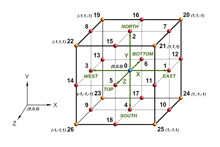
lattice within which the propagation of data takes place - the directional values of the function of the probability density distribution for the momentum of the fictitious particle with mass m = 1. Propagation occurs only in selected directions of space and is determined by the type of lattice mesh used. Networks are denoted in DmQn style, where m is the number of dimensions of space and n is the number of grid directions. For example, the D3Q19 network is a three-dimensional network in which propagation occurs to neighboring nodes in 19 directions out of 27 possible.
Figure 2 presents the layout of grid directions and numbering convention of lattice nodes. The grid is composed of 8 voxels and 27 computational nodes. The lattice-Boltzmann method is a stochastic method. The domain of the function is the number of grid directions, while the values of the momentum density function are real numbers from the range 0-1. The directions of space X, Y, Z are marked in green. The nodes of the D3Q19 grid are marked in red together with the blue color nodeForAutoThreading 0. An additional 8 nodes of the D3Q27 grid were marked in orange.

2. Lattice D3Q19 (nodes: blue + red) and D3Q27 (nodes: blue + red + orange)


